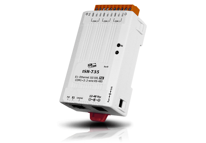
Contents:
- About tSH-700 gateways
- Review of gateway WEB interface
- Configuration of Modbus Master devices connection to Modbus Slave
- Configuration of Modbus RTU devices connection to Modbus ASCII on various rates
- How to reset tSH-700 gateway to factory default settings
About tSH-700 gateways
Gateways of tSH-700 series allow coordinating devices operation with various RS-232/422/485 interfaces on different rates and with various COM port parameters.
For example, the gateway allows connecting two devices to any protocol: the first device with 9600 N81 parameters, the second one with 115200 E71 parameters.

These gateways allow converting Modbus RTU and Modbus ASCII protocols.

In addition to the above mentioned features, the gateways with 3 COM ports allow connecting two Master devices to a Slave bus.
In this mode, the gateway can operate with any protocol, including Modbus RTU/ASCII.
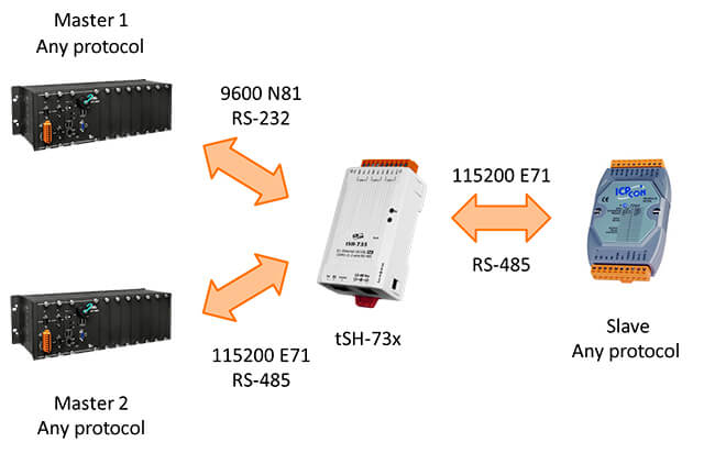
The tSH-700 gateway series includes several modifications that differ in COM ports amount and type. The differences are given in the table.
| Without isolation | With isolation | RS-232 | RS-485 | Features |
|---|---|---|---|---|
| tSH-722 | tSH-722i | 2 | - |
Converter |
| tSH-725 | tSH-725i | - | 2 | |
| tSH-724 | tSH-724i | 1 | 1 | |
| tSH-732 | tSH-732i | 3 | - |
Converter, splitter |
| tSH-735 | tSH-735i | - | 3 | |
| tSH-734 | tSH-734i | 2 | 1 |
The gateway configuration is performed through a WEB interface over an Ethernet port.
Review of gateway WEB interface
Let us move to the WEB interface review and the gateway configuration.
Go to the device IP address.
For the primary search, eSearch Utility can be used .
Once a password is entered, we get to the Home page where the gateway current settings are displayed.
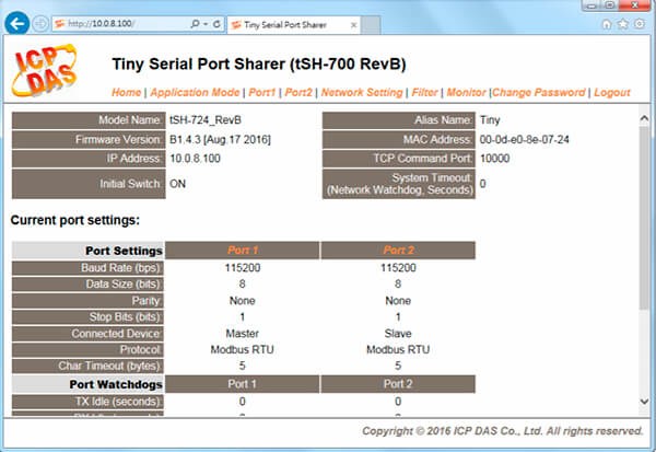
In the Application Mode tab, the gateway operation mode can be configured.
Gateways with 2 COM ports
For gateways with 2 COM ports, we will see the following menu.
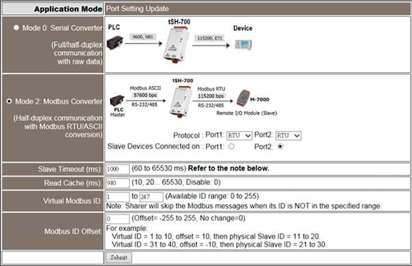
Serial Converter mode
This function allows connecting two devices on different rates, interfaces and a COM port parameters.
Any protocol can be applied.
Full-duplex communication is available only for RS-232 and RS-422 when transmitting data of less than 512 bytes due to inner buffer restriction.
Modbus Converter mode
This function is similar to the mode above, however it also allows converting Modbus RTU/ASCII protocols.
Slave Timeout parameter
In these modes, it is required to set the correct time for Slave device response in the Slave Timeout field, for sending the next request from the gateway buffer. In your Master device, the response await time must be larger than that of a bus (cannot be less than 100ms).
How to choose Slave Timeout correctly?
Slave Timeout can be calculated according to the formula:
A = Max. Response Time of all Slave devices in a bus (in ms).
B = A + 100 = Specify this value in the Slave Timeout field in tSH-700.
C1 = B + 100 = Specify this value in the Response Timeout field in Master device in “1 Master to 1 Slave” scheme.
C2 = B + B = Specify this value in the Response Timeout field in Master device in “2 Masters to 1 Slave” scheme.
As an example, let us connect any device to RS-485 network with Modbus RTU protocol.
Max. Response Time of a device is 172 ms.

In the bus, specify Slave Timeout equal to B = A+100 = 272 ≈ 300 ms.

In the Master device, in accordance with “2 Master - 1 Slave “ scheme, specify Response Timeout equal to C2 = B + B = 300 + 300 = 600 ms.

Accordingly, the Master device polling timing must be greater than C2 = 600 ms, for instance, 700 ms (so that the gateway buffer will not get overflown).
Read Cache parameter
This function allows speeding up obtaining similar data from a gateway buffer.
If the data has already been requested, then during Read Cache time these data will be received from a buffer. The buffer stores the data of a read function only.
tSH-71x/72x/73x gateways allow storing 32/16/10 request/responses, accordingly.
Virtual Modbus ID parameter
This function allows throwing commands from the ID outside the specified range.
Modbus ID Offset parameter
This function allows ID offset on a gateway output.
Gateways with 3 COM ports
For gateways with 3 COM ports, we will see another menu.
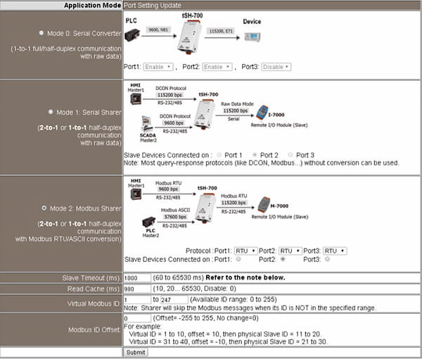
Serial Converter mode
This function allows connecting два devices on different rates, interfaces and a COM port parameters.
Any protocol can be applied.
Full-duplex communication is available only for RS-232 and RS-422 when transmitting data of less than 512 bytes due to inner buffer restriction.
Serial Sharer mode
This function allows two Master devices to connect to a Slave device’s bus.
Any protocol, various baud rates and COM port parameters can be used.
You only need to choose which COM port would be a Slave.
Modbus Sharer mode
This function allows two Modbus Master devices to connect to the Slave devices’ bus.
Conversion of Modbus RTU/ASCII protocols and operation on various baud rates and COM port parameters are possible.
You only need to choose which COM port would be a Slave and which Modbus protocol to use.
In Port tab, COM port parameters can be configured.

CRC/LRC Confirm parameter
This parameter checks the correctness of CRC control sum in a command upon request and response. If the sum is incorrect then the command is declined.
Char Timeout parameter
This parameter sets the waiting time (in bytes) after the response is received from the Slave device. If the time expires, then the response is deemed to have been received and the gateway begins processing this response.
The parameter of 5 bytes can be used by default.
TX Idle / RX Idle parameter
If TX / RX do not transmit/receive data for a certain period, the gateway will be rebooted.
In Network Settings tab, the gateway network parameters can be set.

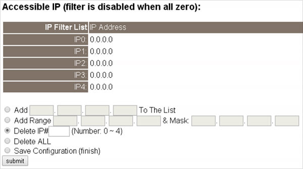
In Filter tab, the trusted IP addresses can be set.
In Monitor tab, the status of data transfer/receipt of each port can be checked.

Configuration of Modbus Master devices connection to Modbus Slave
This mode is only available for a gateway with 3 COM ports.
Choose a Modbus Sharer mode.
Let us configure tSH-735 gateway as an example.
In Application Mode field, choose Modbus Sharer mode and RTU or ASCII protocol.
Also, specify a COM port, which the Slave device will be connected to.

In Slave Timeout field, specify the waiting time of the Slave device for sending the next request from the gateway buffer, for instance 500 ms.

The rest parameters can be left unchanged.
Then, in Port tab, COM port parameters must be configured.

Once the parameters are saved, the gateway is ready to be an arbitrator in “2 Modbus Master – 1 Modbus Slave” scheme (connection of several Slave devices is possible).
Also, in this mode, Modbus RTU/ASCII protocols on various baud rates can be converted.
On Master devices, specify Response Timeout that is larger, than Slave Timeout parameter.
It can be calculated according to the formula:
- A = Max. Response Time of all devices in a bus (in ms).
- B = A + 100 = Specify this value in the Slave Timeout field in tSH-700.
- C2 = B + B = Specify this value in the Response Timeout field in Master device in “2 Masters - 1 Slave” scheme.
In our example, Response Timeout for both Master devices is equal to 500 + 500 = 1000 ms.
Also, the Master device polling timing must be greater than Response Timeout C2 = 1000 ms, for instance, 1100 ms (so that the gateway buffer will not get overflow).
Configuration of Modbus RTU devices connection to Modbus ASCII on various baud rates
For the gateway with 2 COM ports, choose Modbus Converter mode.

For the gateway with 3 COM ports, choose Modbus Sharer mode, as in the previous example.

In Slave Timeout field, specify the waiting time of the Slave device for sending the next request from the gateway buffer, for instance, 500 ms.

The rest parameters can be left unchanged.
Then, in Port tab, configure the parameters of the required COM ports.

Once the configuration is saved, the gateway is ready to convert Modbus RTU/ASCII protocols on various baud rates.
On Master devices, specify Response Timeout that is greater, than Slave Timeout parameter.
It can be calculated according to the formula:
- A = Max. Response Time of all devices in a bus (in ms)
- B = A + 100 = Specify this value in the Slave Timeout field in tSH-700 gateway
- C1 = B + 100 = Specify this value in the Response Timeout field in Master device in “1 Master - 1 Slave” scheme
In our example, Response Timeout for the Master device is equal to 500 + 100 = 600 ms.
Also, the Master device polling timing must be greater than Response Timeout C1 = 600 ms, for instance, 700 ms (so that the gateway buffer will not get overflown).
How to reset tSH-700 gateway to factory default settings
Turn off the gateway power.
Move the switch to INIT position.
Supply the gateway with power.
Now, you can find the gateway on a factory IP address - 192.168.255.1.
You can change it via , and then move a switch to RUN position.
Turn off the gateway power, and supply the gateway with power again.
Now, the gateway will be available at a new IP address and the factory password can be used to access the gateway settings.

