Industrial Ethernet networks often need to stay connected when a cable or link fails. A ring provides an alternative route, but the redundant path must be controlled to prevent a Layer 2 loop. CTC Union addresses this with u-Ring, a proprietary redundancy mechanism available on supported managed Ethernet switches.
For larger or mixed network structures, CTC Union also provides u-Chain and Sub Ring. Together, these options cover closed rings, links to existing redundant networks and additional redundant segments.
Three Redundancy Options
| Configuration | Network structure | Typical use |
|---|---|---|
| u-Ring | Closed ring | Redundant network built from compatible CTC Union switches |
| u-Chain | Open chain linked to another redundant network | Connection to an existing STP or RSTP environment |
| Sub Ring | Additional ring segment | Extension of a u-Ring or u-Chain topology |
In a u-Ring, one path is kept out of normal forwarding so that the network remains loop free. If an active link is lost, the standby path is released and traffic can continue around the remaining side of the ring.
u-Chain is intended for projects where a CTC Union segment needs to connect to an existing redundant network. The external switches do not become part of the proprietary u-Ring protocol; the boundary between the two networks must therefore be checked with the actual hardware and firmware used in the project.
Sub Ring adds further redundant sections to a larger u-Ring or u-Chain design.
Recovery Performance Is Device Specific
u-Ring is available across current CTC Union managed switch families, but recovery figures are not identical for every model.
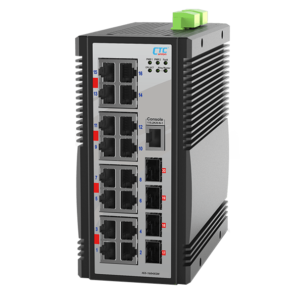
For the CTC Union IGS-1604XSM, the manufacturer specifies recovery in less than 10 ms with up to 250 devices. Other switch families may have different limits or recovery values, so the specification of the selected hardware should always be used for project design.
Network recovery and application recovery are not the same thing. A controller, camera or supervisory system may still see brief packet loss while the forwarding path changes. The relevant question is whether the application can tolerate that interruption.
Build Redundancy Around the Failure Scenario
A ring protocol protects only against failures covered by the network design. If both sides of the ring follow the same cable route, a single physical incident can still interrupt both paths. Shared power supplies, switches, fibre components and other common points of failure require the same attention.
Monitoring also matters. After a successful failover, communication may continue normally even though the network is operating without full redundancy. The failed link should therefore be detected and repaired before a second fault occurs.
Verify the Design Before Commissioning
Acceptance criteria should be defined before the network goes into service. The allowable communication interruption, the affected endpoints and the expected application behaviour should all be clear.
A representative link should then be disconnected under realistic traffic conditions. The test should confirm that communication is restored as expected and that the connected application remains within its permitted limits.
For u-Chain installations, the response of the connected STP or RSTP network should be included in the test.
Selecting the Right CTC Union Switch
The appropriate u-Ring solution depends on more than recovery time. Port configuration, copper or fibre connectivity, environmental requirements, power architecture and the planned network topology all influence the hardware choice.
IPC2U can help match these requirements to suitable industrial Ethernet switches and review the proposed redundancy topology for the application.