In this article, you will learn about the Modbus TCP protocol, which is the evolution of the Modbus RTU protocol.
Contents:
- Where to send a Modbus TCP command?
- Description of the Modbus TCP protocol
- Modbus TCP command types
- How do I send a Modbus TCP command to read discrete output? Command 0x01
- How to send a Modbus TCP command to read a digital input? Command 0x02
- How to send a Modbus TCP command to read the analog output? Command 0x03
- How to send a Modbus TCP command to read an analog input? Command 0x04
- How do I send a Modbus TCP command to write discrete output? Command 0x05
- How do I send a Modbus TCP command to record analog output? Command 0x06
- How do I send a Modbus TCP command to write multiple discrete pins? Command 0x0F
- How do I send a Modbus TCP command to write multiple analog outputs? Command 0x10
- Modbus TCP request errors
- Programs for working with the Modbus TCP protocol
- Equipment with Modbus TCP support
Where to send a Modbus TCP command?
In an Ethernet network, the device address is its IP address. Typically, devices are on the same subnet, where IP addresses differ by the last two digit 192.168.1.20 when using the most common subnet mask 255.255.255.0.
The interface is an Ethernet network, the data transfer protocol is TCP / IP.
The TCP port used is: 502.
Description of the Modbus TCP protocol
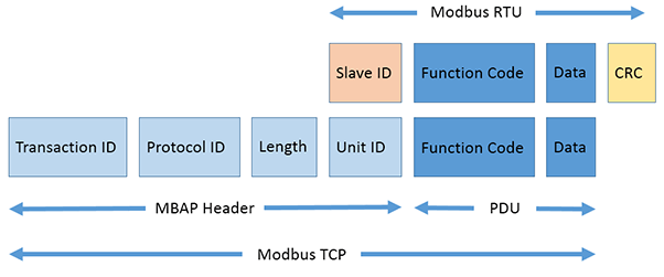
The Modbus TCP command consists of a portion of the Modbus RTU message and a special header.
From the Modbus RTU message, the SlaveID address at the beginning and the CRC checksum at the end are removed, which forms the PDU, the Protocol Data Unit.
The following is an example of a Modbus RTU request for obtaining the AI value of the holding registers from registers # 40108 to 40110 with the address of the device 17.
11 03 006B 0003 7687
| 11 | Device address SlaveID (17 = 11 hex) |
| 03 | Function Code (read Analog Output Holding Registers) |
| 006B | Address of the first register (40108-40001 = 107 = 6B hex) |
| 0003 | The number of required registers (reading 3 registers from 40108 to 40110) |
| 7687 | Checksum CRC |
We drop the address of the SlaveID device and the CRC checksum and get the PDU: 03 006B 0003
03 006B 0003
At the beginning of the received PDU message, a new 7-byte header is added, which is called MBAP Header (Modbus Application Header). This header has the following data:

Transaction Identifier: 2 bytes are set by the Master to uniquely identify each request. Can be any. These bytes are repeated by the Slave device in the response, since the responses of the Slave device may not always be received in the same order as the requests.
Protocol Identifier: 2 bytes are set by the Master, will always be 00 00, which corresponds to the Modbus protocol.
Length: 2 bytes are set by the Master, identifying the number of bytes in the message that follow. It is counted from Unit Identifier to the end of the message.
Unit Identifier: 1 byte is set to Master. It is repeated by the Slave device to uniquely identify the Slave device.
Total we get:
| Modbus RTU | Slave ID | Inquiry | CRC |
|---|---|---|---|
| Modbus RTU | 11 | 03 006B 0003 | 7687 |
| Modbus TCP | 0001 0000 0006 11 | 03 006B 0003 | |
| Modbus TCP | MBAP Header | PDU | |
| Modbus TCP | ADU, Application Data Unit | ||
Where:
| 0001 | Transaction identifier | Transaction Identifier |
| 0000 | Protocol identifier La | Protocol Identifier |
| 0006 | Length (6 bytes are followed) | Message Length |
| 11 | The device address (17 = 11 hex) | Unit Identifier |
| 03 | Function code (read Analog Output Holding Registers) | Function Code |
| 006B | First address register (107 = 40108-40001 = 6B hex) | Data Address of the first register |
| 0003 | The number of required registers (read 3 registers 40108 by 40110) | The total number of registers |
In the response from the Modbus TCP Slave device we get:
0001 0000 0009 11 03 06 022B 0064 007F
Where:
| 0001 | Transaction identifier | Transaction Identifier |
| 0000 | Protocol identifier | Protocol Identifier |
| 0009 | The length (9 bytes are followed) | Message Length |
| 11 | The device address (17 = 11 hex) | Unit Identifier |
| 03 | Function code (read Analog Output Holding Registers) | Function Code |
| 06 | The number of bytes later (6 bytes are followed) | Byte Count |
| 02 | Value of the high register bit (02 hex) | Register value Hi (AO0) |
| 2B | Early discharge value register (2B hex) | Register value Lo (AO0) |
| 00 | Value of the high register bit (00 hex) | Register value Hi (AO1) |
| 64 | Value of the low register bit (64 hex) | Register value Lo (AO1) |
| 00 | Value of the high register bit (00 hex) | Register value Hi (AO2) |
| 7F | Early discharge value register (7F hex) | Register value Lo (AO2) |
The analog output register AO0 has the value 02 2B HEX or 555 in the decimal system.
The analog output register AO1 has the value 00 64 HEX or 100 in the decimal system.
The analog output register AO2 has the value 00 7F HEX or 127 in the decimal system.
Modbus TCP command types
Here is a table with the codes for reading and writing the Modbus TCP registers.
| Function Code | What the function does | Value type | Access type | |
|---|---|---|---|---|
| 01 (0x01) | Reading DO | Read Coil Status | Discrete | Reading |
| 02 (0x02) | Reading DI | Read Input Status | Discrete | Reading |
| 03 (0x03) | Reading AO | Read Holding Registers | 16 bit | Reading |
| 04 (0x04) | Reading AI | Read Input Registers | 16 bit | Reading |
| 05 (0x05) | One DO recording | Force Single Coil | Discrete | Recording |
| 06 (0x06) | Recording one AO | Preset Single Register | 16 bit | Recording |
| 15 (0x0F) | Multiple DO recording | Force Multiple Coils | Discrete | Recording |
| 16 (0x10) | Recording multiple AOs | Preset Multiple Registers | 16 bit | Recording |
How do I send a Modbus TCP command to read discrete output? Command 0x01
This command is used to read the values of the DO digital outputs.
The PDU request specifies the start address of the first DO register and the subsequent number of required DO values. In the PDU, the DO values are addressed starting from zero.
The DO values in the response are in one byte and correspond to the value of the bits.
The bit values are defined as 1 = ON and 0 = OFF.
The low bit of the first data byte contains the DO value whose address was specified in the request. The remaining values of DO follow the increasing value to the highest value of the byte. Those. from right to left.
If less than eight DO values were requested, the remaining bits in the response will be filled with zeros (in the direction from the low to high byte). Field Byte Count Number byte further indicates the number of full data bytes in response.
| Byte | Request | Byte | Answer |
|---|---|---|---|
| (Hex) | Field name | (Hex) | Field name |
| 01 | Transaction identifier | 01 | Transaction identifier |
| 02 | 02 | ||
| 00 | Protocol identifier | 00 | Protocol identifier |
| 00 | 00 | ||
| 00 | Message length | 00 | Message length |
| 06 | 04 | ||
| 01 | Device address | 01 | Device address |
| 01 | Functional code | 01 | Functional code |
| 00 | Address of the first byte of register Hi | 01 | Number of bytes more |
| 00 | Address of the first byte of register Lo | 02 | The value of register DO 0-1 |
| 00 | Number of registers Hi Byte | ||
| 02 | Number of registers Lo Byte | ||
The output states DO0-1 are shown as 02 hex values, or in the binary system 0000 0010.
The DO1 value will be the second to the right, and DO0 will be the first on the right (low-order bit).
The other six bits are filled with zeros to the full byte, because They were not requested.
| Channels | - | - | - | - | - | - | DO 1 | DO 0 |
| Bits | 0 | 0 | 0 | 0 | 0 | 0 | 1 | 0 |
| Hex | 02 | |||||||
How to send a Modbus TCP command to read a digital input? Command 0x02
This command is used to read the values of digital inputs DI.
The query and response for DI is similar to the query for DO.
| Byte | Request | Byte | Answer |
|---|---|---|---|
| (Hex) | Field name | (Hex) | Field name |
| 01 | Transaction identifier | 01 | Transaction identifier |
| 02 | 02 | ||
| 00 | Protocol identifier | 00 | Protocol identifier |
| 00 | 00 | ||
| 00 | Message length | 00 | Message length |
| 06 | 04 | ||
| 01 | Device address | 01 | Device address |
| 02 | Functional code | 02 | Functional code |
| 00 | Address of the first byte of register Hi | 01 | Number of bytes more |
| 00 | Address of the first byte of register Lo | 03 | The value of register DI 0-1 |
| 00 | Number of registers Hi Byte | ||
| 02 | Number of registers Lo Byte | ||
The output states of DI 0-1 are shown as 03 hex values, or in the binary system 0000 0011.
The DI1 value will be the second to the right, and the value of DI0 will be the first right (low-order bit).
The other six bits are filled with zeros.
How to send a Modbus TCP command to read the analog output? Command 0x03
This command is used to read the values of the analog outputs AO.
| Byte | Request | Byte | Answer |
|---|---|---|---|
| (Hex) | Field name | (Hex) | Field name |
| 01 | Transaction identifier | 01 | Transaction identifier |
| 02 | 02 | ||
| 00 | Protocol identifier | 00 | Protocol identifier |
| 00 | 00 | ||
| 00 | Message length | 00 | Message length |
| 06 | 07 | ||
| 01 | Device address | 01 | Device address |
| 03 | Functional code | 03 | Functional code |
| 00 | Address of the first byte of register Hi | 04 | Number of bytes more |
| 00 | Address of the first byte of register Lo | 02 | Register value Hi (AO0) |
| 00 | Number of registers Hi Byte | 2B | Register value Lo (AO0) |
| 02 | Number of registers Lo Byte | 00 | Register value Hi (AO1) |
| 64 | Register value Lo (AO1) | ||
The output states AO0 are shown as 02 byte 2B hex, or in the decimal system 555.
The output states AO1 are shown as the byte values 00 64 hex, or in the decimal system 100.
How to send a Modbus TCP command to read an analog input? Command 0x04
This command is used to read the values of analog inputs AI.
| Byte | Request | Byte | Answer |
|---|---|---|---|
| (Hex) | Field name | (Hex) | Field name |
| 01 | Transaction identifier | 01 | Transaction identifier |
| 02 | 02 | ||
| 00 | Protocol identifier | 00 | Protocol identifier |
| 00 | 00 | ||
| 00 | Message length | 00 | Message length |
| 06 | 07 | ||
| 01 | Device address | 01 | Device address |
| 04 | Functional code | 04 | Functional code |
| 00 | Address of the first byte of register Hi | 04 | Number of bytes more |
| 00 | Address of the first byte of register Lo | 00 | Register value Hi (AI0) |
| 00 | Number of registers Hi Byte | 0A | Register value Lo (AI0) |
| 02 | Number of registers Lo Byte | 00 | Register value Hi (AI1) |
| 64 | Register value Lo (AI1) | ||
The output states AI0 are shown as 00 0A hex values, or in the decimal system 10.
The output states AI1 are shown as the byte values 00 64 hex, or in the decimal system 100.
How do I send a Modbus TCP command to write discrete output? Command 0x05
This command is used to record one value of the DO digital output.
The value of FF 00 hex sets the output to ON.
The value 00 00 hex sets the output to OFF.
All other values are invalid and will not affect the output state.
The normal response to such a request is an echo (a repeat request in the response), is returned after the DO state has been changed.
| Byte | Request | Byte | Answer |
|---|---|---|---|
| (Hex) | Field name | (Hex) | Field name |
| 01 | Transaction identifier | 01 | Transaction identifier |
| 02 | 02 | ||
| 00 | Protocol identifier | 00 | Protocol identifier |
| 00 | 00 | ||
| 00 | Message length | 00 | Message length |
| 06 | 06 | ||
| 01 | Device address | 01 | Device address |
| 05 | Functional code | 05 | Functional code |
| 00 | Hi Register Address byte | 00 | Hi Register Address byte |
| 01 | Lo Register Address byte | 01 | Lo Register Address byte |
| FF | Hi Byte Meaning | FF | Hi Byte Meaning |
| 00 | Lo Byte Meaning | 00 | Lo Byte Meaning |
The output status of DO1 has changed from OFF to ON.
How do I send a Modbus TCP command to record analog output? Command 0x06
This command is used to record one value of the analog output AO.
| Byte | Request | Byte | Answer |
|---|---|---|---|
| (Hex) | Field name | (Hex) | Field name |
| 01 | Transaction identifier | 01 | Transaction identifier |
| 02 | 02 | ||
| 00 | Protocol identifier | 00 | Protocol identifier |
| 00 | 00 | ||
| 00 | Message length | 00 | Message length |
| 06 | 06 | ||
| 01 | Device address | 01 | Device address |
| 06 | Functional code | 06 | Functional code |
| 00 | Hi Register Address byte | 00 | Hi Register Address byte |
| 01 | Lo Register Address byte | 01 | Lo Register Address byte |
| 55 | Hi Byte Meaning | 55 | Hi Byte Meaning |
| FF | Lo Byte Meaning | FF | Lo Byte Meaning |
The output status of AO0 has changed to 55 FF hex, or in the decimal system 22015.
How do I send a Modbus TCP command to write multiple discrete pins? Command 0x0F
This command is used to record multiple values of DO's digital output.
| Byte | Request | Byte | Answer |
|---|---|---|---|
| (Hex) | Field name | (Hex) | Field name |
| 01 | Transaction identifier | 01 | Transaction identifier |
| 02 | 02 | ||
| 00 | Protocol identifier | 00 | Protocol identifier |
| 00 | 00 | ||
| 00 | Message length | 00 | Message length |
| 08 | 06 | ||
| 01 | Device address | 01 | Device address |
| 0F | Functional code | 0F | Functional code |
| 00 | Address of the first byte of register Hi | 00 | Address of the first byte of register Hi |
| 00 | Address of the first byte of register Lo | 00 | Address of the first byte of register Lo |
| 00 | Number of registers Hi Byte | 00 | Number of recorded reg. Hi byte |
| 02 | Number of registers Lo Byte | 02 | Number of recorded reg. Lo bytes |
| 01 | Number of bytes more | ||
| 02 | Byte Value | ||
The output status of DO1 has changed from OFF to ON.
The DO0 output state remains OFF.
How do I send a Modbus TCP command to write multiple analog outputs? Command 0x10
This command is used to record multiple values of the analog output AO.
| Byte | Request | Byte | Answer |
|---|---|---|---|
| (Hex) | Field name | (Hex) | Field name |
| 01 | Transaction identifier | 01 | Transaction identifier |
| 02 | 02 | ||
| 00 | Protocol identifier | 00 | Protocol identifier |
| 00 | 00 | ||
| 00 | Message length | 00 | Message length |
| 0B | 06 | ||
| 01 | Device address | 01 | Device address |
| 10 | Functional code | 10 | Functional code |
| 00 | Address of the first byte of register Hi | 00 | Address of the first byte of register Hi |
| 00 | Address of the first byte of register Lo | 00 | Address of the first byte of register Lo |
| 00 | Number of registers Hi Byte | 00 | Number of recorded reg. Hi byte |
| 02 | Number of registers Lo Byte | 02 | Number of recorded reg. Lo bytes |
| 04 | Number of bytes more | ||
| 00 | Byte value Hi AO0 | ||
| 0A | Byte value Lo AO0 | ||
| 01 | Byte value Hi AO1 | ||
| 02 | Byte value Lo AO1 | ||
The output state of AO0 has changed to 00 0A hex, or in decimal system 10.
The output status of AO1 has changed to 01 02 hex, or in the decimal system 258.
Modbus TCP request errors
If the device can not process it after receiving the request, the response will be sent with an error code.
The response will contain the modified Function code, its high-order bit will be 1.
Example:
| It was | Became |
|---|---|
| Functional code in the query | Functional error code in response |
| 01 (01 hex) 0000 0001 | 129 (81 hex) 1000 0001 |
| 02 (02 hex) 0000 0010 | 130 (82 hex) 1000 0010 |
| 03 (03 hex) 0000 0011 | 131 (83 hex) 1000 0011 |
| 04 (04 hex) 0000 0100 | 132 (84 hex) 1000 0100 |
| 05 (05 hex) 0000 0101 | 133 (85 hex) 1000 0101 |
| 06 (06 hex) 0000 0110 | 134 (86 hex) 1000 0110 |
| 15 (0F hex) 0000 1111 | 143 (8F hex) 1000 1111 |
| 16 (10 hex) 0001 0000 | 144 (90 hex) 1001 0000 |
Sample request and response with error:
| Byte | Request | Byte | Answer |
|---|---|---|---|
| (Hex) | Field name | (Hex) | Field name |
| 01 | Transaction identifier | 01 | Transaction identifier |
| 02 | 02 | ||
| 00 | Protocol identifier | 00 | Protocol identifier |
| 00 | 00 | ||
| 00 | Message length | 00 | Message length |
| 06 | 03 | ||
| 0A | Device address | 0A | Device address |
| 01 | Functional code | 81 | Functional code with changed bit |
| 04 | Address of the first byte of register Hi | 02 | Error code |
| A1 | Address of the first byte of register Lo | ||
| 00 | Number of registers Hi Byte | ||
| 01 | Number of registers Lo Byte | ||
Explanation of error codes
| 01 | The received function code can not be processed. |
| 02 | The data address specified in the request is not available. |
| 03 | The value contained in the query data field is an invalid value. |
| 04 | An unrecoverable error occurred while the slave attempted to perform the requested action. |
| 05 | The slave has accepted the request and processes it, but it takes a long time. This response prevents the host from generating a timeout error. |
| 06 | The slave is busy processing the command. The master must repeat the message later when the slave is freed. |
| 07 | The slave can not execute the program function specified in the request. This code is returned for an unsuccessful program request using functions with numbers 13 or 14. The master must request diagnostic information or error information from the slave. |
| 08 | The slave detected a parity error when reading the extended memory. The master can repeat the request, but usually in such cases, repairs are required. |
Programs for working with the Modbus TCP protocol
Below are the programs that will help you easily interact with Modbus TCP devices.
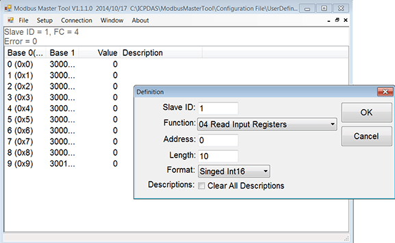
Modbus Master Tool with support for Modbus RTU, ASCII, TCP. Download

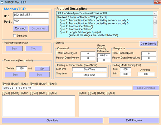
Modbus TCP client with support for Modbus TCP. Download


