Overview/history of flash memory (SSD)
The common term flash memory refers to digital memory chips that can store data in a non-volatile manner and without the use of energy. The correct term would be flash EEPROM, an abbreviation for electrically erasable programmable read-only memory.
Whereas it was previously common practice to store data permanently using magnetic (later also optical and magneto-optical) means without the need for a backup power supply (e.g. supplied by batteries or capacitors), the development of EPROMs represented a compact, robust and reliable way of storing data. However, the application was still very cumbersome, as the data could only be erased in its entirety and only by irradiating the components with UV light.
EEPROMs represented a further development that made it possible to erase data bit by bit in a targeted manner using electrical control voltages. Flash memories are a special case of EEPROMs, which are also non-volatile and can be erased electrically, but only block by block and not individual bits. The development team felt that this block-by-block erasure reminded them of a flash, which gave this form of memory its now familiar name. However, it was this limitation of functionality that made it possible to manufacture the memory chips at all. It was this that made their widespread use economically viable and sensible.
Originally closely linked to the development of digital cameras, flash EEPROMs have now established themselves as the de facto standard for mass data storage in the IT world. As they are gradually replacing magnetic drives in particular, the term SSD (short for solid state drive) has become established to distinguish them from drives with moving parts, although strictly speaking they are not drives.
Formerly introduced primarily as space-saving, compact memory cards and later as hard disk replacements in classic 2.5“ HDD housings in the IT sector, flash memory is now available in many mechanical and electrical formats (2.5”, M.2, DOM, mSATA, CompactFlash, CFast, SD, microSD, MMC, eMMC etc.).
Technical developments regarding the efficiency of flash memory have also led to new technologies, changes in the structure of the memory cells and access via data interfaces.
Not least due to the mechanically robust concept without moving, rotating parts, which makes flash memory extremely insensitive to vibrations and shocks or impacts, flash memory has become the standard in industrial applications. However, as the requirements and expectations of mass storage media in industry do not always correspond to those in the home or office sector, there is a large selection of flash memory series that are adapted to specific environments and applications. For example, there are flash memories with particularly wide operating temperature ranges or others that are optimized for particularly fast read/write speeds, longevity, data integrity or freedom from loss during the storage process (capturing).
In this area, Industrial Personal Computer 2U GmbH works together with a number of memory manufacturers who specialize in the production of components to industrial standards (ADATA, Innodisc, Apacer, etc.), but also offers the use of high-quality components from the consumer/office sector (Samsung, Intel, SanDisk, etc.) at the customer's request if cost efficiency is the primary consideration when purchasing. True to our motto of working with each customer to find the optimum solution for every project, we offer a wide range of options. Please contact us!
Communication protocols for flash memory (SSDs)
ATA /PATA/IDE and ATAPI:
AT Attachment (ATA for short) is a standard for parallel data transfer between storage media and the corresponding hardware interface of a computer. The standard was originally developed by Western Digital as a proprietary technology under the name Integrated Drive Electronics, or IDE for short.
The AT Attachment Packet Interface (ATAPI for short) uses the physical ATA interface and extends the protocol so that SCSI packets can be transferred. These SCSI commands extend the application range of ATA beyond pure hard disk operation so that devices such as removable disk drives, optical drives and tape drives can also be used. ATAPI is also used with Serial ATA (see below).
The functions of ATA are usually taken over by its successor, Serial ATA, in modern computers. Since the introduction of Serial ATA, the parallel ATA standard has often been referred to as PATA or P-ATA. Today, the terms ATA, PATA and IDE are often used interchangeably.
ATA devices are connected to the 40-pin interface of the host via a ribbon cable (ATA-40). Originally intended for notebooks, there are also special forms of interface for compact embedded box PCs that also transmit the supply voltage (+5 V). These are called ATA-44 for 2.5″ hard disks, where the number indicates the number of plug contacts.
With ATA, 16-bit words are transmitted in parallel via 16 data lines. This principle, originally conceived to increase data transfer rates, reached its conceptual limits in the course of the development of higher clock speeds. With parallel buses, the higher the data transfer rate, the higher the risk of undesirable side effects that hinder a further increase in the transfer rate. These include increasing asynchrony of the parallel data lines and crosstalk, i.e. undesirable mutual interference between the lines. In addition, the unspecified bus termination and the ground-related signals in ATA severely restrict the usable cable length. Serial ATA uses serial transmission to avoid these problems.
SATA:
Even in the first SATA design, the data rate of 1.5 Gbit/s was 50% higher than that of the last PATA generation at just 133 MB/s.
Serial ATA, SATA or S-ATA for short, is a computer interface for data exchange with hard disk drives, solid-state drives and other storage devices. “ATA” stands for the originally parallel transfer protocol AT Attachment, whose name refers to the IBM Personal Computer/AT and compatible devices (see above).
Serial ATA was developed by Intel in 2000 from the older ATA/ATAPI standard. The decision was made to switch from a parallel bus design to a bit-serial point-to-point connection in which the data is transferred serially (bit by bit) instead of 16-bit words as in the old ATA standards. SATA offers three main advantages over its predecessor: higher data transfer rates, simplified cable routing and the possibility of hot swapping, i.e. the exchange of data carriers during operation. Since the introduction of Serial ATA, the older ATA standard has been referred to as Parallel ATA (PATA) to differentiate it. Both connection types were initially found in parallel on the motherboard; since 2010, however, ATA connections have been increasingly omitted.
Topologically, SATA is a point-to-point connection, which means that a SATA connection on the motherboard is only intended for one device. Serial ATA is not limited to hard disk drives - tape drives, DVD drives and burners or memory card readers can also be used via the ATAPI protocol. The external eSATA interface is or was also in competition with Universal Serial Bus, FireWire and Thunderbolt.
NVMe via M.2:
NVM Express (NVMe for short) is a software protocol that was published in 2011 to connect flash memory via the physical PCI Express interface without the need for manufacturer-specific drivers. NVM stands for “non-volatile memory” and refers to SSDs. NVMe aims to increase speed, especially for parallel accesses, which are common in multithreading, by reducing latency and instruction overhead.
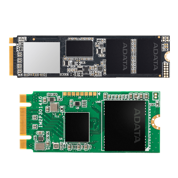
M.2, formerly known as Next Generation Form Factor (NGFF), is a specification for internal computer expansion cards and corresponding ports. This specification was developed to replace mSATA. Thanks to its smaller and more flexible dimensions and extended functions, M.2 is particularly suitable for connecting SSDs or flash memory, especially in compact devices such as notebooks or tablets, but also compact embedded box PCs. Due to the high data transfer rates, especially via the PCIE x4 bus, M.2 has also found its way into board design for desktop or 19” rackmount PCs.
The M.2 standard supports three bus systems: PCI Express (up to version 4.0), SATA Revision 3.x and USB 3.0. There are M.2 variants that offer up to four PCI Express lanes (up to 4 × 16 Gbit/s, also known as Gen4), a SATA Revision 3.x (6 Gbit/s) and/or a USB 3.0 port (5 Gbit/s) via one connection. This means that both PCI Express and SATA storage can be connected via M.2, and both bus systems can be used in parallel on each port.
SSDs are normally backwards compatible. For example, a Gen4 SSD will also work in a Gen2 socket at a correspondingly reduced speed. With older mainboards in particular, it can happen that an M.2 socket shares lines with one of the SATA interfaces and cannot be used at the same time. It can also happen that when an M.2 socket is occupied, one or more PCIe slots are no longer available or are only available at a reduced speed. This mainly affects motherboards with several M.2 sockets. When using a single SSD, you should always use the first socket that is closer to the CPU.
Physical formats of flash memory (SSDs)
The history of flash memory is closely linked to that of the digital camera. This was one of the first applications in which digital (image) data was to be stored non-volatilely on a very small scale. Flash memory is still used today in the form of memory cards. However, the small dimensions and low weight compared to the large amount of data that can be stored quickly led to further applications, such as use in removable data carriers, such as memory sticks or USB sticks, and in some cases permanently installed in mobile devices such as audio players or mobile phones/smartphones. It quickly became clear that flash memory also has advantages over magnetic (hard disk, floppy disc etc.), optical (CD-ROM) or magneto-optical (minidisc, MO disc etc.) mass storage devices in stationary operation. In order to be able to use these in existing hardware architectures, they were initially offered in formats and with interfaces that enabled them to be used in PCs using existing connections (SATA) and drive bays (primarily 2.5“ and 1.8”). However, more space-efficient formats such as DOM (Disc-On-Module), mSATA or M.2 soon followed, which then also offered newer, faster interfaces (NVMe, PCIe x4). Here is an overview of the most important and most common formats:
2.5” SATA SSD:
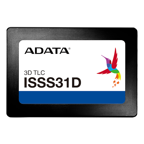
Flash memory that is accessed via the widely used SATA interface and is installed in a classic 2.5” hard disk housing. It can therefore be found in most PCs and can also be used as a replacement for hard disk drives that have become obsolete. Industrial 2.5 SATA SSD.
DOM
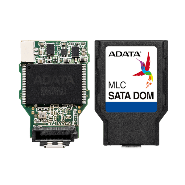
In contrast to the 2.5” SSD, there is no need for a bulky housing that has to be connected via a cable; instead, the memory module is plugged directly into the drive interface. In order to avoid spatial conflicts, DOMs are usually offered in different designs (vertically upright or horizontally to the left or right). In addition to DOMs that are connected via SATA (aka SATA DOM), models with the outdated IDE/PATA interfaces are also available for older PCs (PATA DOM). This means that older computers that fulfill important tasks and therefore should not or cannot be replaced can be retained. Industrial IDE and SATA DOM.
mSATA:
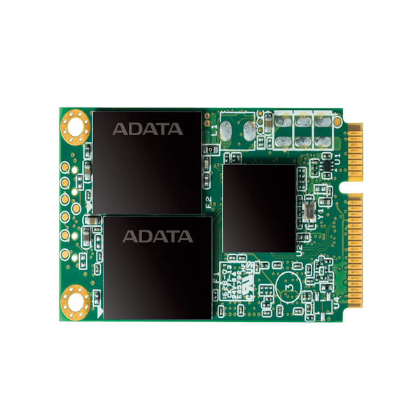
Flash memory in mSATA format (abbreviation for mini-SATA) is a very space-efficient mass storage variant. In contrast to the 2.5” SSDs and DOMs, which are operated on the SATA interface, these require a separate interface that must already be planned and installed in the board design. Physically identical to the PCI Express Mini format, this is electrically identical to the SATA interface and offers a corresponding read/write speed. The interface is significantly more compact and the flash memory module lies flat above the board. Flash memory in the mSATA format has a width of only around 30mm and a length of 51mm (full-size) or 27mm (half-size), depending on the version. This enables a very compact computer design.
Secured by a screw, the module is also very resistant to vibrations and shocks, making it a good alternative for industrial or mobile applications in particular.
M.2:
The M.2 format can be seen as the successor to mSATA. Similarly compact, it also offers the option of addressing via NVMe (PCIe x4) in addition to SATA, which allows a significantly faster data rate (increase by a factor of ten compared to SATA 3.0). The M.2 standard allows module widths of 16mm, 22mm and 30mm. The length is between 30mm and 110mm. The dimensions are specified in the product description using a four-digit code, with the first two digits indicating the width in millimeters and the last two the length. Currently 2230, 2242, 2260 and 2280 are commonly used. M.2 modules are plugged into a port parallel to the board, similar to the predecessor mSATA, and fixed in place with a screw. As the M.2 standard theoretically enables operation via SATA, USB and PCIe buses, and therefore a variety of applications beyond use as an interface for flash memory, so-called keying has also been introduced. This is a form of connector coding using cut-outs in the module's PCB, which must correspond with corresponding (...) in the socket in order to fit together mechanically. The most common are A- and E-Key for modules for functional expansion and B- and M-Key for mass storage. Nevertheless, caution is advised here, because the fact that a module fits mechanically into a certain port does not necessarily mean that it is also signal-compatible. For the best possible performance, it is important to compare the interface data with that of the card to be used. We will be happy to help you select suitable modules.
Memory cards:
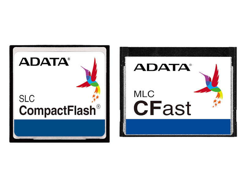
Primarily designed for use as removable storage media, a number of memory cards based on flash memory technology have also found their way onto the market. In addition to SD cards, which are also widely used in the mobile communications and digital photography sectors, CompactFlash and CFast cards are particularly popular in the industrial IT environment.
eMMC:
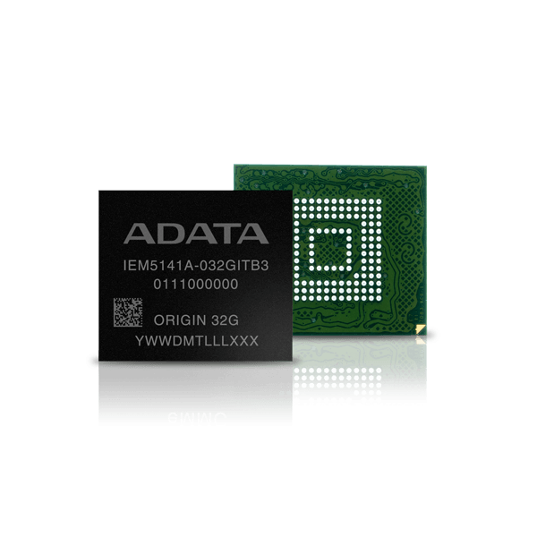
The eMMC plays a special role here. Based on the increasingly rare MMC (Multi Media Card), a memory card standard developed jointly by Siemens and Samsung, the eMMC (abbreviation for: embedded MMC) is a permanently soldered flash memory solution that is always used where space restrictions prevent the integration of a slot to accommodate memory modules, e.g. in very small single board computers (SBC).
